Level of difficulty: Advanced
Three-way switches control lights and receptacles from two points: for example, a light in a hallway that can be operated from the first floor and second
floor. Or, a light in a garage that can be turned on/off from the garage and the kitchen or pantry, etc. What you need for light switch installation:
- Three-way switch
- Three-way cable with another for ground wire (four total)
- Terminal screws
- No.12 wire
- Lineman's pliers or hacksaw
- Sharp knife or slitting tool
- Wire strippers
- Hand brace
- Drill with long auger electrician's bit
- Coil of electrician's fish wire
- Grounding screws
- Black tape
Three-way switches require a three-wire cable: the power wire, the neutral wire, and the traveller or switch wire.
The cable should also have a ground wire, or a total of four wires in the cable. The system also requires three-way switches. The switches are wider
than regular single-pole switches and they have three terminal screws on the side (sometimes back) of the switch housing. Two terminals will be on one side
of the switch housing; one terminal on the other side.
Four-way switches have four terminals. This switch works in combination with two three-way switches to control electricity to lights and receptacles
from three locations. All of the four terminals are brass colored. They support hot conductors (traveller wires), which receive and transfer electricity
from each of the three-way switches. The toggle on a four-way switch is NOT marked "OFF" and "ON. " These markings are the only way to tell the difference
between it and a double-pole switch, which is labeled "OFF" and "ON."
It is advisable to use No. 12 wire for residential, indoor wiring. No. 14 wire is acceptable if the circuit is protected at 15 amperes. (Canadian code
requires the use of #14 wire for interior application.)
Caution:
Local and provincial codes should be checked before starting any wiring project. Most codes dictate that all wire connections must be placed inside
a switch, receptacle or junction box. If wires going to switches and fixtures are going to be exposed to dampness, use wire designated for damp
locations. Be sure to obtain any required electrical permits before beginning work. |
ESTIMATING WIRE NEEDED
The information and illustrations are based on the use of non-metallic, sheathed cable (often called by the brand name Romex). To figure materials needed,
measure the distance between the new switch and the power source. Add an extra foot for every connection you will make along the line. Then, to provide
a margin for error, add 20% more. For example, if you measure 12 feet of cable between a new switch and existing fixture, add another 2 feet for the two
connections, making the total 14 feet. Then add 20%, about 3 feet, to the total. To do this job, you would need 17 feet of cable.
WORKING WITH WIRE
To make wire connections, the wire must be pulled through boxes at least 6 inches, cut, and then stripped of insulation. Here is the procedure to follow:
- Cut the cable to the proper length using lineman's pliers or a hacksaw.
- With a sharp knife or slitting tool, slit the outer sheathing, being very careful not to cut the insulation covering the wires inside the cable.
If possible, lay the cable on a flat, firm surface to slit it properly. You may also use a cable ripper.
- Peel back the sheathing and trim it square.
- With wire strippers, put single wires in the proper size groove in the handle (12 for No. 12 gauge wire). Twist the stripper or rotate it 360 degrees,
sliding the insulation off the wire as it breaks loose under the cutting blades. Remove 3/4 to 1 inch of insulation.
- Splice wires together and top with a wire connector.
ADDING NEW WIRING
This involves pulling wires through studs and rafters in back of the wall covering (plaster, gypsum wallboard, etc.). You will need a hand brace, a
drill with a long electrician's bit, a coil of electrician's fish wire and lots of patience.
In wiring three-way switches, the power wire is connected to the COMMON terminal, usually marked "COM. " The location of this common terminal may vary
according to the manufacturer of the switch. Check the switch. If not marked, the common terminal may be color-coded black or brass.
In the following illustrations, track each wire with a finger or pencil to its conclusion at the fixture. This way, you will ensure all connections are
made properly.
Note that the shadings of the wires in the illustrations represent actual color. See color key in each figure.
Caution:
When working with electricity, always turn off the power at the main service (fuse or circuit breaker) panel before you start working. Be sure the
circuit is completely dead!
|
 Option
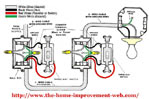
1. Fixture Controlled by Two Switches: Power Through a Switch Box Option
1. Fixture Controlled by Two Switches: Power Through a Switch Box
Two three-way switches control one light with the electric power coming through the first switch, flowing to the second switch, and then to the
light fixture. The ground wire goes through both switch boxes and the ceiling light box and it is connected at all junctions, except the light,
with a pigtail (short piece of wire) and wire connector. The hot wire in the drawing is black and is connected to the COM terminal. The neutral
wire is white. Track each with a finger to its conclusion at the light fixture to ensure proper connection. Some light fixtures with a chain pull
have a ground connection.
(Click Image or here to enlarge/print Diagram) |
 Option
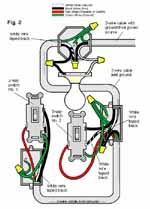
2. Fixture Controlled by Two Switches: Power Through Light Option
2. Fixture Controlled by Two Switches: Power Through Light
Two three-way switches control one light with the electric power coming through the light on a two wire cable. In order to code the white wire,
which is used as a power wire from the light fixture through the switches, black electrician's tape is wrapped around the wire in the boxes. This
way, if you or someone else goes into the boxes for repairs, the white wire taped black will indicate a hot wire. Even when taped black, the white
wire may never be used to bring power to the fixture terminal. The red traveller (switch) wire runs just between the two switches, not the light.
Note connections of the ground wire.
(Click Image or here to enlarge Diagram) |
 Option
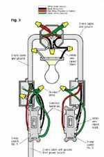
3. Fixture Between Two Three-Way Switches: Power Through Switch Option
3. Fixture Between Two Three-Way Switches: Power Through Switch
Light is controlled by two three-way switches with the light between the switches and the power first going through a switch, then to the light,
and onto the second three-way switch. The ground wire is pigtailed with a wire connector at the switch boxes and the ceiling box. Grounding screws
often are furnished with boxes and are green.
Tip:The traveller wire goes through the light ceiling box and that the white wire is taped black between the fixture and second switch.
(Click Image or here to enlarge/print Diagram)
|
 Option
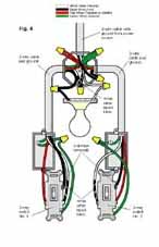
4. Fixture Between Two Switches: Power Through Light Option
4. Fixture Between Two Switches: Power Through Light
This light is between switches with the power source from the light. Three-wire cable with a ground wire is used for this connection. The power
is routed first through the light ceiling box and then flows to the switches.
Tip:White neutral wire from the power source is connected directly to the light fixture. The black or hot wire is routed to a switch and then is
fed back through the connections via a white wire taped with black electrician's tape to indicate that it is hot. The traveller wires are connected
at the fixture box.
(Click Image or here to enlarge/print Diagram)
|
 Option
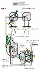
5. End-of-Run Lights Controlled by Two Three-Way Switches Option
5. End-of-Run Lights Controlled by Two Three-Way Switches
These end-of-run lights are controlled by two three-way switches with a two-wire cable power source coming through the first three-way switch.
Tip:The white or neutral wire goes completely through the connection system with pigtail connections at both switches and the first light box. Only
two-wire cable with ground is needed for the boxes at the lights. Traveller wires (red) connect the three-way switches without going further in
the system
(Click Image or here to enlarge/print Diagram)
|
 Option
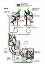
6. Two Three-Way Switches Control Two Lights: Power Through Light Option
6. Two Three-Way Switches Control Two Lights: Power Through Light
End-wired lights are controlled with two three-way switches with power routed through the light boxes to two-wire cable to the two switches.
Tip:Look at how power is connected at lights: White wire taped with black electrician's tape from the nearest switch to a traveller wire that connects
the second or end light, then pigtailed to the brass fixture terminal. All wire is utilized this way without waste. Both the white wire taped black
and the traveller wire (usually red) indicate hot wires, if switches/lights are reworked.
(Click Image or here to enlarge/print Diagram)
|
 Option
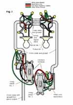
7. Two Lights Between Two Three-Way Switches: Power Through Switch Option
7. Two Lights Between Two Three-Way Switches: Power Through Switch
These lights between switches have the electrical power coming through a switch. Second switch is an end-wired or end-of-run switch. Both three-wire
and two-wire cable with ground are used.
Tip:The traveller wire is connected in the light ceiling boxes, with a length of neutral wire taped black to indicate a hot wire. The ground
wire is pigtailed throughout. Neutral wire bypasses first three-way switch.
Use double cable hookup between lights to handle the multiple wires
(Click Image or here to enlarge/print Diagram)
|
 Option
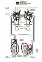
8. End-Wired Switches: Power Through Light Option
8. End-Wired Switches: Power Through Light
Power through the lights to three-way switches has two-wire cable and ground between the light boxes and three-wire cable and ground at the switches.
White or neutral wire taped with black electrician's tape is used as black power wire to make connections throughout. Grounding wires are pigtailed
to the light fixture boxes, and to the switch box terminals. The switches operate both lights, but the wiring ensures that if one bulb should burn
out, the other will still work.
(Click Image or here to enlarge/print Diagram)
|
© 2004 The Home Improvement Web Directory All rights reserved
Note: This article contents are subject to our disclaimer.
|